
Consideration must be taken over where to install your Acoem Dynoptic Opacity, Dust or Particulate monitor. There are a number of points to evaluate before selecting the installation location on your stack or duct, including the following:
- Accessibility
- Vibration
- Gas flow within the stack
- Liquid aerosols
- Temperature
- Cable routes
- Earth connection
- Air purge tubing
- Legislation
This article focuses on Gas Flow within the Stack. The stack gas flow characteristics at the measurement point should be considered carefully when locating the instrument. Ideally the monitor heads should be positioned on a straight section of duct with a uniform gas flow. This requires the mounting location to have no abrupt changes in diameter, no bends, no inlets or outlets and no intrusions or protrusions, within at least 5 duct diameters of the head downstream, and 2 duct diameters upstream.
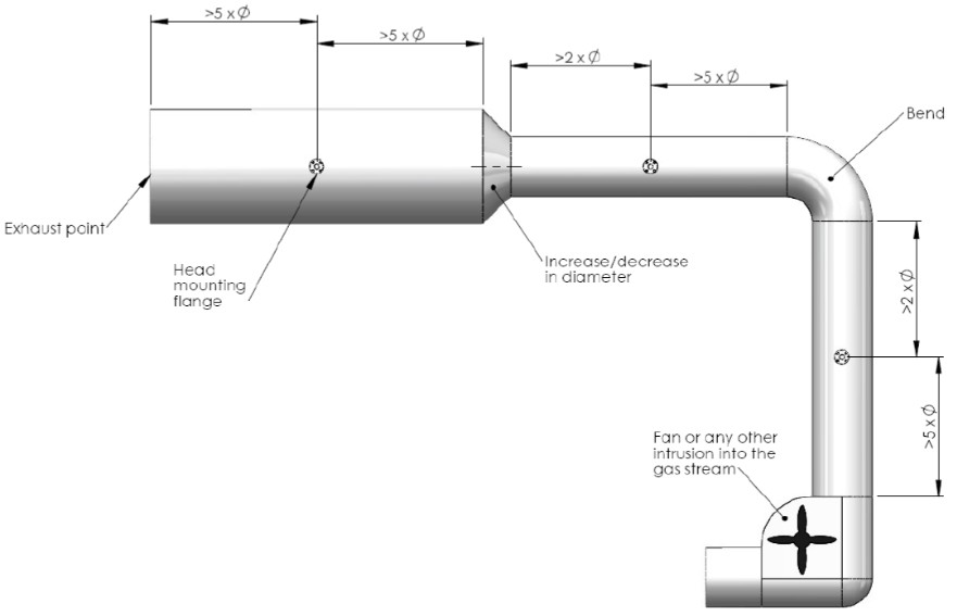
Ideally the measurement point should be located at least 5 duct diameters from the exhaust point, see image above. Where suitable sample planes exist in both vertical and horizontal sections of the duct, the vertical section is preferable.
Please note. The heads should never be positioned at the bottom of a horizontal duct or angled duct, as particulate matter will fall under gravity towards the head and potentially cause the optics to become dirty more quickly.
For more information about ACOEM Dynoptic’s range of opacity, dust and particulate monitors please visit www.dynoptic.com or email dynoptic@acoem.com

